Hi Dave,
It seems like there is a large following error. ~1400 counts / 12290 = 0.112 inches
Have you tried increasing gains to reduce the
errors.
On a minor not the output is only going to ~ 160 counts of 2048 DAC counts (~ 8% of the available range).
The dual loop looks correct. But I don't think it makes any sense to try dual loop with such a low performance inner loop.
Regards TK
| Group: DynoMotion |
Message: 9093 |
From: daves3891 |
Date: 2/3/2014 |
| Subject: Re: Motor Tuning [2 Attachments] |
|
Thank Tom,
The servo seems to be really overpowered for the axis since it doesn't take a lot of signal to get it moving fast.
I will try increasing the gains. What kind of following error would be good? Should the output have a more rapid frequency?
Also when I do start tuning the second loop, what PID settings would I start at? Would they be similar to the first loop?
Just to clarify, is the ch1->Dest the motor/rotary and the ch0->Output the linear scale?
Thanks
Dave
|
|
| Group: DynoMotion |
Message: 9094 |
From: Tom Kerekes |
Date: 2/3/2014 |
| Subject: Re: Motor Tuning |
Hi Dave, Yes increasing the gains will cause the system to respond to reduce errors faster. Of course too high of gains will correct too much too quickly and become unstable. The following error depends on your requirements. But I would think a 0.1 inch error would be bad for even such a large system. Your requirements are likely to be different for different situations. On high speed rapids from one end to the other you probably don't care what the following error is. But at slower cutting speeds it may be more critical. What is the reasoning on adding the linear scales if the Servo errors put the position off by 0.1 inches? The settings for the outer loop depend on the system so it is hard to say. If the inner loop is doing a great job of controlling velocity then simple P
gain should work reasonably well (bigger the error - move faster to reduce the error/as the target gets closer slow down). HTH Regards TK
| Group: DynoMotion |
Message: 9095 |
From: daves3891 |
Date: 2/3/2014 |
| Subject: Re: Motor Tuning |
|
Tom,
Which loop would I use the most I gain in?
Do I need to scale one of the encoder counts to match the others in terms of counts per inch?
Dave
|
|
| Group: DynoMotion |
Message: 9096 |
From: Tom Kerekes |
Date: 2/3/2014 |
| Subject: Re: Motor Tuning |
Hi Dave,
Again all values depend on your system. It is hard to say a numerical value. Adjust it until you get the desired effect. I think you definitely want more I gain in your inner loop based on your last plot. This is because of the very large error fro a very long time. An Integrator is good for driving errors that persist for a long time to zero.
I highly recommend you get the single loop working better before going on to more complicated things.
It shouldn't be necessary to match the encoder resolutions. The inner loop is like a velocity amplifier with some gain. It doesn't really matter what the gain is because you can adjust the gains of the outer loop to command more or less to get the desired response. But that being said it might be less confusing if you
do. You could then switch from single to dual loop and leave KMotionCNC at the same resolution.
Regards TK
| Group: DynoMotion |
Message: 9097 |
From: daves3891 |
Date: 2/3/2014 |
| Subject: Re: Motor Tuning |
|
Thank Tom,
I will defiantly get the inner loop tuned a lot better before I move on to dual.
Just to confirm,
When I use the C program for dual loop (ch1->Dest += ch0->Output)
ch1->Dest is the inner (Motor) loop and ch0->Output is the outer (Scale) loop ?
Thanks again
Dave
|
|
| Group: DynoMotion |
Message: 9098 |
From: Tom Kerekes |
Date: 2/3/2014 |
| Subject: Re: Motor Tuning |
yes
| Group: DynoMotion |
Message: 9099 |
From: daves3891 |
Date: 2/4/2014 |
| Subject: Re: Motor Tuning |
|
Tom,
One more quick question.
What should the integrator limit be set to? Should it be around the same as the output limit?
How do you tune this parameter?
Thanks
Dave
|
|
| Group: DynoMotion |
Message: 9100 |
From: daves3891 |
Date: 2/4/2014 |
| Subject: Re: Motor Tuning |
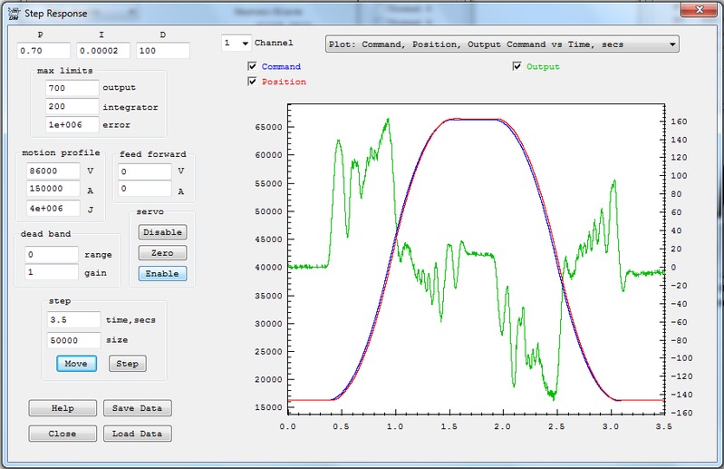
Tom, I started tuning my other axis. This one consists of a master/slave setup.
I am attaching the results I am currently getting.
If I add more D value it becomes unstable and it currently has a little vibration in some spots but it does settle to the correct position.
Does the output look unstable? I am not sure what I am looking for here
Dave
|
|
|
@@attachment@@
|
| Group: DynoMotion |
Message: 9101 |
From: Tom Kerekes |
Date: 2/4/2014 |
| Subject: Re: Motor Tuning |
Hi Dave, Normally yes. When moving at constant max speed (with no error) the Integrator is what maintains the necessary output to maintain cruising speed. So the Integrator limit should be set large enough for this. Under normal circumstances the Integrator limit will never be reached and could be set to infinity with no change in response. However the main purpose of this parameter is to help with a classic issue referred to as Integrator Wind Up. In some special and unusual cases such as with the amplifier disabled (and the axis still enabled with a small error) that persists for a very long time, or any circumstance where an error is not corrected for very long time, the Integrator will continue to ramp to higher and higher values (infinity). When the system finally responds (amplifier is
re-enabled, obstruction is removed) the result will be a huge overshoot (slam!). Regards TK
| Group: DynoMotion |
Message: 9102 |
From: Tom Kerekes |
Date: 2/4/2014 |
| Subject: Re: Motor Tuning [2 Attachments] |
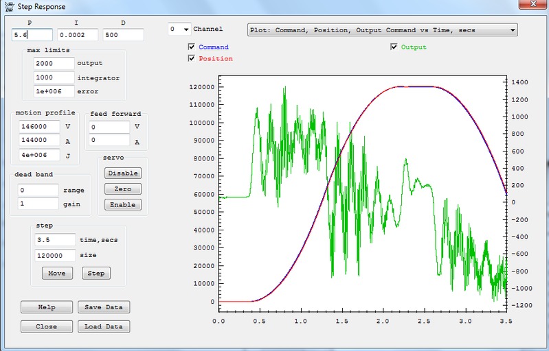
Hi Dave,
It looks marginally unstable. Zooming in on position error you can see 40~50 Hz oscillation.
You didn't include your filters screen so I have to
guess, but it looks like you have some low pass filtering. Otherwise the high D gain of 500 would cause spikes of 500 in the output.
Following error is still over 1000 counts. Can you see that?
I would expect higher I gain would reduce that. But you will
probably need to make the system more stable to allow higher I gain. Try reducing P and D and increasing I while observing following error and oscillations.
I think the lower frequency oscillations may be your lead screw (not servo related).
You might try a Bode
Plot.
A Lead-Lag filter may work better than so much D gain to add phase margin.
HTH Regards TK
| Group: DynoMotion |
Message: 9103 |
From: daves3891 |
Date: 2/4/2014 |
| Subject: Re: Motor Tuning [2 Attachments] |
Thanks Tom, I am pretty new to the servo tuning stuff. The system is rack and pinion, not lead screw. And I haven't enabled any filter, but I will double check it. I have been trying to re tune this axis from scratch (P0.1, D0, I0) and I don't really know what I am doing. It seems like some values will work well with a small move but not a large one and same with the opposite.
Should I be tuning with step or move? How long of a move do I tune with to begin? Is the basic idea to start increasing P first? If so how high do I go before I stop and move to the D value?
Dave
|
|
| Group: DynoMotion |
Message: 9104 |
From: Tom Kerekes |
Date: 2/4/2014 |
| Subject: Re: Motor Tuning |
Hi Dave,
Sorry Control Theory isn't easy. There isn't any simple 1, 2, 3 step approach to it. Every system is different. You must spend some time understanding what the parameters do and how your system responds.
Rack and pinion often have high friction and backlash. Those are likely to limit your performance and will be very difficult to include in the linear scale control loop.
I think you do have a low pass filter.
Starting from scratch doesn't really help. Better to start with something with better performance.
Use the "Move" button for testing.
Theoretically things should be dynamically the same whether sitting still or moving fast. But there are some subtle nonlinear differences. Like friction might be higher when sitting still. If friction is slowing/dampening response then things may go unstable while moving. Be sure not to be moving too fast for your system and saturating the output.
But basically increase P until things begin to go unstable (over shoot, oscillations). Then back off some. BTW if you set a small following error then the system will simply disable before it becomes violently unstable. Then increase D and it should become more stable and possibly allow higher P. D adds damping. Think of it like submersing a pendulum in thick honey. Unlike P and I that make the system respond more quickly, D tends to make things slower and smoother. But at some point more D will make the system more unstable itself. This happens because big forces to try to slow things down are delayed by the system response and actually make things worse. After P and D are optimized they should be backed off sacrificing some performance to allow a good margin of stability. Then I gain can be introduced to reduce slower persistent errors. Any I gain at
all adds a beautiful result that the average error over the long term will always be exactly equal to zero. It makes it impossible to have even a +1 count error indefinitely because the integrator will keep increasing the motor torque higher and higher until the error is corrected. The level of I gain determines how fast this will happen. The disadvantage is that I is very destabilizing and causes overshoot. In order to have zero average error any negative error must be balanced with an equal positive error. So for example if the trajectory takes off and the servo lags behind, then at some point the Integrator will require it to run ahead to balance.
HTH Regards TK
| Group: DynoMotion |
Message: 9105 |
From: daves3891 |
Date: 2/4/2014 |
| Subject: Re: Motor Tuning |
|
Tom,
I will give it try again in the morning.
Am I just looking for overshoot at the peak and base of the graph? Or is it when it overshoots the whole time?
I also have a couple Konnect boards arriving soon so I will be sure to take a bunch of pictures of the full retrofit when completed
Thanks
Dave
|
|
| Group: DynoMotion |
Message: 9109 |
From: daves3891 |
Date: 2/5/2014 |
| Subject: Re: Motor Tuning |
|
Tom,
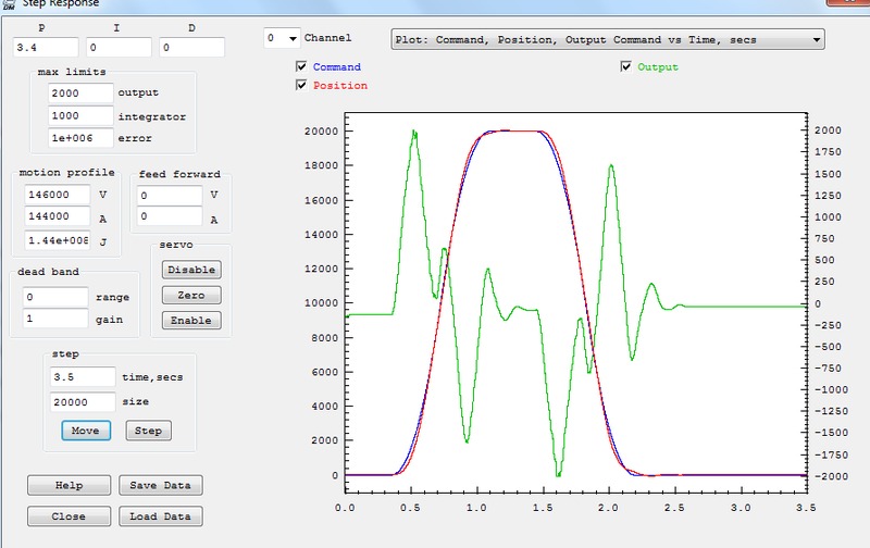
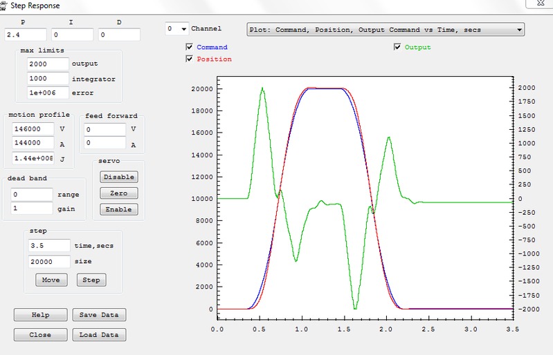
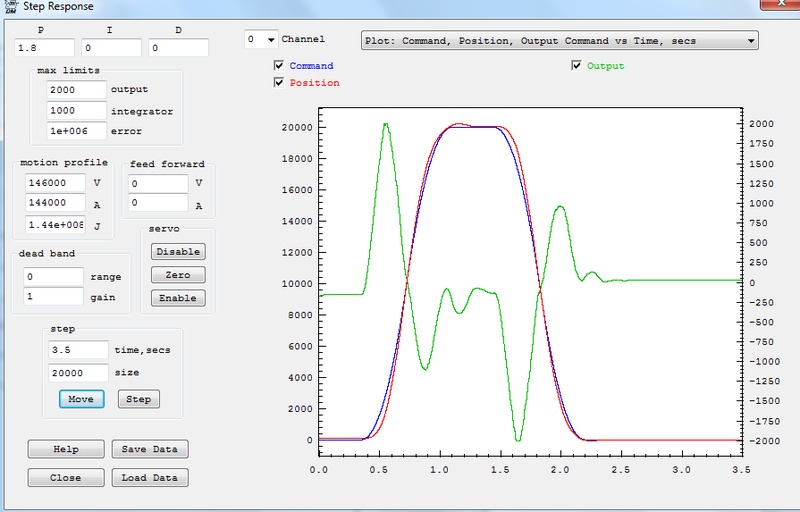
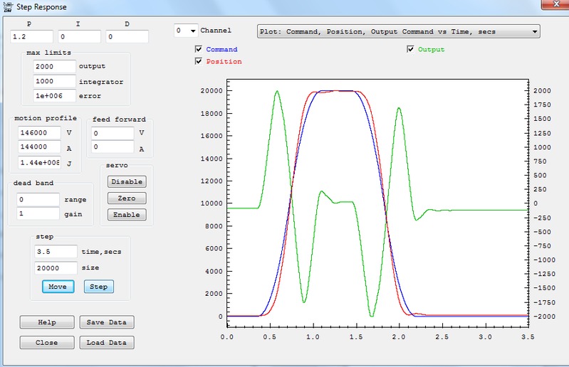
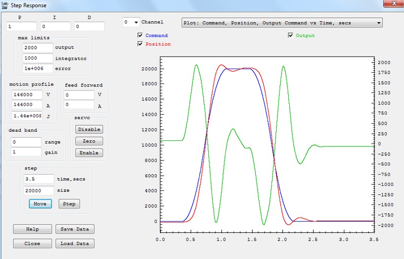
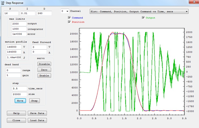
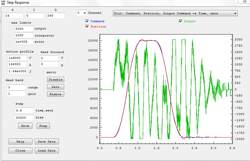
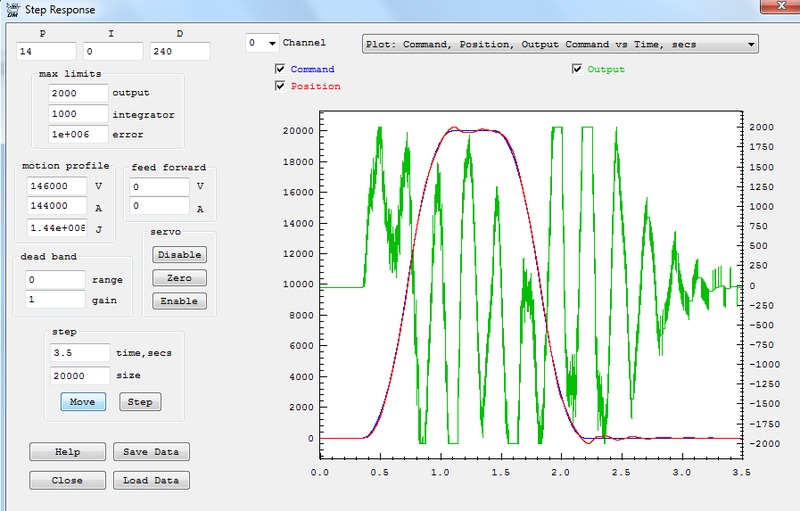
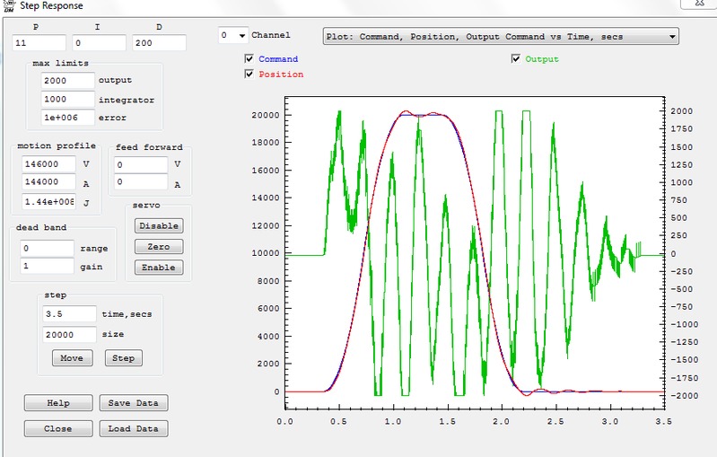
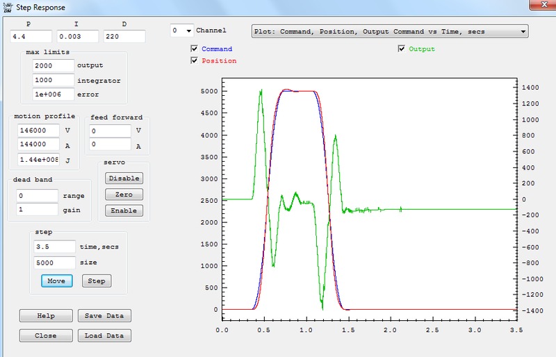
I have tried some more tuning today and saved some graphs.
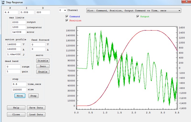
The first thing I did was start with a low P and no ID and started to increase them slowly till it had some vibration. It look like it started to overshoot around 4.4 and vibration at 6.5
I tried to play with the D some with a P of 3.8
It didn't seem to really help the positioning at all but just added noise in the output.
Any advice on the graphs would be appreciated
Dave
|
|
|
@@attachment@@
|
| Group: DynoMotion |
Message: 9114 |
From: daves3891 |
Date: 2/5/2014 |
| Subject: Re: Motor Tuning |
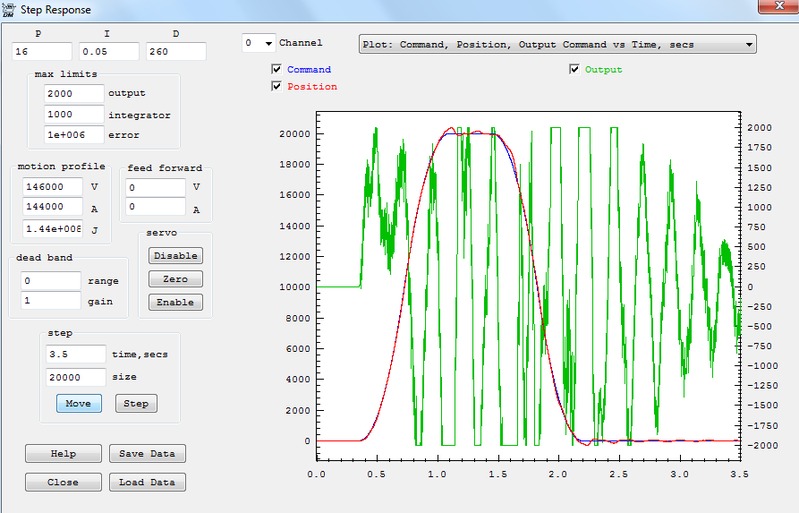
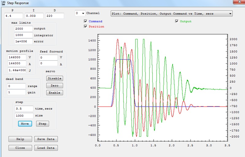
So I did get the gain up a lot and it seems to be getting close to tuned I think?? Adding I does start to make it unstable tho..
Am I on the right track?
Dave
|
|
|
@@attachment@@
|
| Group: DynoMotion |
Message: 9115 |
From: Tom Kerekes |
Date: 2/5/2014 |
| Subject: Re: Motor Tuning [18 Attachments] |
Hi Dave,
P=3.8 D=120 look the best to me. The spikes on the output are caused by sudden changes in position of 1 encoder count cause the output to spike 120 DAC counts. You can smooth those with a Low Pass Filter. Set the last filter to 2nd order Low Pass 500Hz Q=1.4 and the output should be much smoother. Then try to increase D further.
Regards TK
| Group: DynoMotion |
Message: 9130 |
From: daves3891 |
Date: 2/6/2014 |
| Subject: Re: Motor Tuning |
|
Tom,
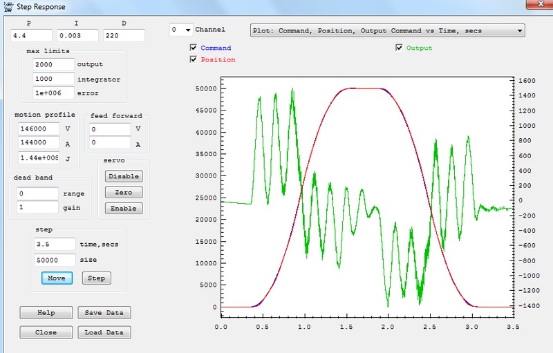
I did some more tuning this morning and that filter seemed to help a lot.
I added a little more P and some I to get to position.
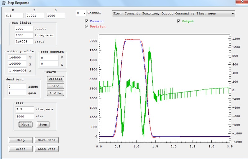
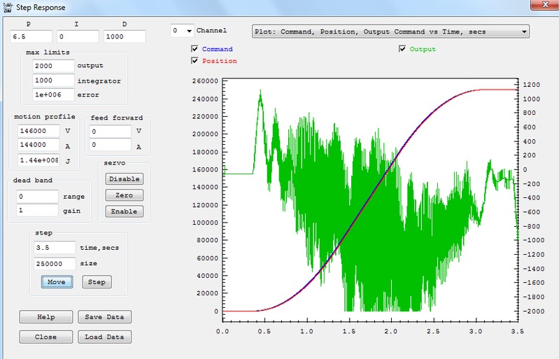
Now I have tried a range of move distances from 1000 to 150000 and some of the smaller ones seem to have stability issues?
Is there any filter that can correct this?
I have attached the graphs
Thanks
Dave
|
|
| Group: DynoMotion |
Message: 9131 |
From: daves3891 |
Date: 2/6/2014 |
| Subject: Re: Motor Tuning |
|
Looks like the pictures didn't show up.. will try again
|
|
|
@@attachment@@
|
| Group: DynoMotion |
Message: 9136 |
From: daves3891 |
Date: 2/6/2014 |
| Subject: Re: Motor Tuning |
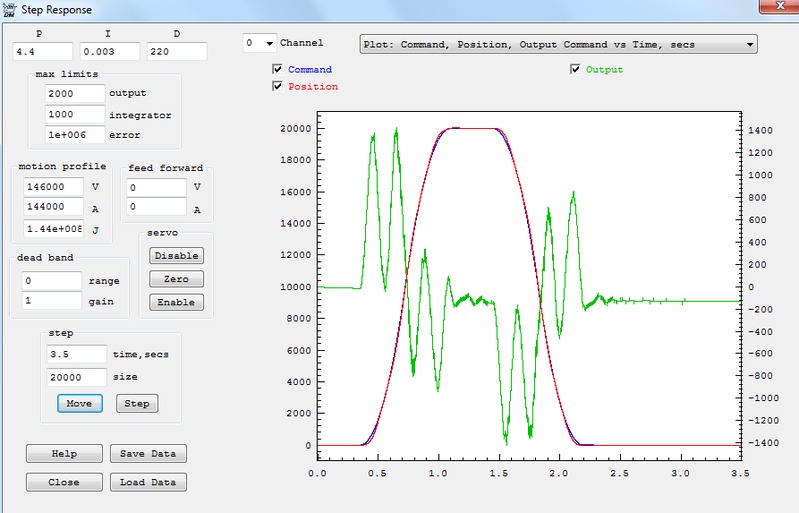
OK, I had to add more gain and crank the D way up but it seems not too bad with various distances now.
The last graph has a little I added to zero out the last bit of error, but this seems to make it overshoot.
Maybe I need to play with the windup?
Let me know what you think
Thanks
Dave
|
|
|
@@attachment@@
|
| Group: DynoMotion |
Message: 9140 |
From: Tom Kerekes |
Date: 2/6/2014 |
| Subject: Re: Motor Tuning |
Hi Dave,
It looks like they all somewhat unstable. Mainly it is hard to see small errors on big moves if you don't zoom in or show error instead of position.
So I think you need to back off on P and or I to be more stable everywhere.
If you do a Bode Plot we may be able to understand things better and come up with a lead/lag filter for a bit higher performance.
If you include the raw data then we can zoom in
ourselves.
Regards TK
| Group: DynoMotion |
Message: 9143 |
From: daves3891 |
Date: 2/6/2014 |
| Subject: Re: Motor Tuning |
|
Tom,
Do you want the data for all the plots?
What is involved in doing the bode plot? Do I just go to the menu and hit start?
Thanks
Dave
|
|
| Group: DynoMotion |
Message: 9152 |
From: Tom Kerekes |
Date: 2/7/2014 |
| Subject: Re: Motor Tuning |
Hi Dave,
Rather than sending many plots with no explanation of what you changed and what is your understanding of what occurred, it would be better if you summarize what you explored and what happened and included the best examples with the data. The idea is for you to learn and for us to help you to understand we need to know what you are thinking so we can agree or disagree. Try and interpret the plots yourself by indicating things like increasing I gain beyond xxx caused
oscillations of xxx amount at xxx frequency.
It seems your system has a relatively low oscillation frequency of 5~10Hz. On a big structure like yours there may be nothing you can do about it. Did you ever post a picture? Different move sizes don't usually have a big effect. Moving or even accelerating shouldn't have an effect on the mechanical dynamics of the system or the servo stability. All you are doing is disturbing things a bit differently,
The trick to a good Bode plot is to get the stimulus correct. Otherwise the result is all noise or meaningless. Basically if the stimulus is too low there will be no meaningful response to measure. If too big the system will saturate or in some abnormal non-linear mode and not represent normal servo correction amplitudes. Please read the manual section and try to make a measurement. We need to know what all you settings were when it was made, the plot, and what the time domain response to the stimulus looks like.
Regards TK
| Group: DynoMotion |
Message: 9162 |
From: daves3891 |
Date: 2/7/2014 |
| Subject: Re: Motor Tuning |
|
Tom,
I figured the PID values in the screen shots would show what I changed, and I did try to explain that I increased value X until Y happened.
I have posted a video of the machine before to explain the size and operation.
I have read the bode section of the manual, but it doesn't make much sense unless you have used it before or know the concept of what the readings are and what to do with them.
I guess I will just keep using trial and error till it works good enough.
|
|
| | | | | | | | | | | | | | | | | | | |
.png)
.png)
.png)